
This original Taito Asuka & Asuka

I was lucky to grap real cheap on a Danish forum. The guy selling it didn't post a picture of the PCB, misspelled the name of the game, and stated that it might be a bootleg. So even though it was an auction, this game went under the radar of other forum users, and I got it for my initial cheap bid. As I later on discovered that this seller is a dirty rotten swindler, I don't feel bad about it.
Anyway, when I first received the game, it played well and was all working and fine. I decided to bring it with me to an SSKT-gathering in Næstved Denmark, as one of my friends there wanted to try it out. I don't have a car myself, so when I'm not able to get e lift with someone else, I travel by train with all my gaming goodies in a suitcase and/or backpack. Sadly Asuka&Asuka didn't quite survive the trip fully functioning. Some of the colours were frakked up

and I didn't have the time on-site to have a look at it. Upon returning home, it was just shelved, until I had a time to look at it.
Months later I decided to have a go at fixing it. I soon discovered, that this PCB suffers from the same Achilles Heel, as many other Taito games from the same period; the Taito SIL-RGB-module

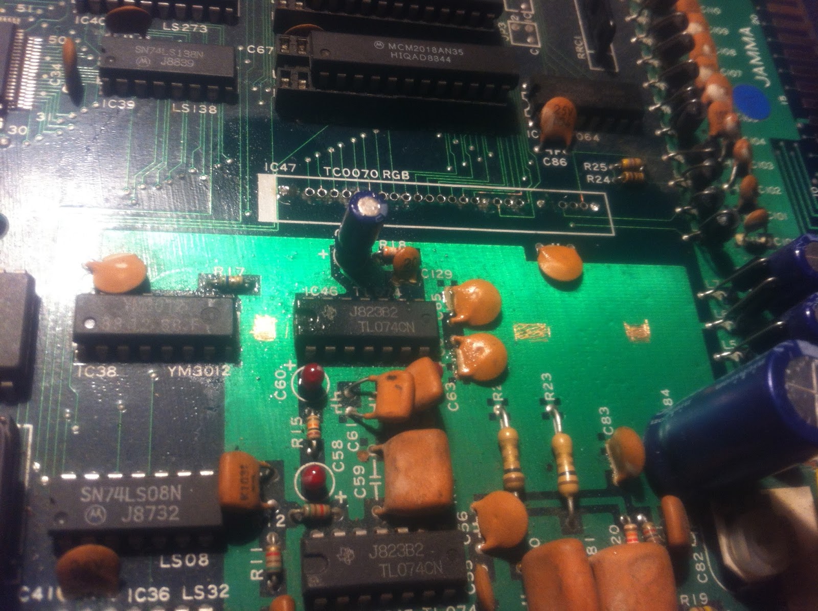
And having a closer look, I could also see, that a reflow from the component side had been attempted earlier on. I found that pressing down on the package made the error go away
Besides that, I also found a large cap on the loose


but I was rather sure, that this was not involved in the colour issue, so went straight on to the RGB-module.
Taito used these type of custom SIL-RGB-modules on a number of their games including i.e. Rainbow Island back in the day, and always mounted them perpendicular to the PCB, instead of making sufficient space on the PCB and bending it down onto the PCB surface. That way it's extremely flimsy and very sensitive to just the slightest bend or bump.
As an initial attempt, I tried doing another reflow from the component side, but without any luck. So I decided on desoldering the thing and mounting it properly. But when I started and gave it just i little yank while desolering, all the pins snapped clean off }:-O


I had a lot of 64-pin reduced size DIL sockets, that I bought as a mistake some time ago (wanted to use them for socketing 68000 CPUs, but didn't look closely enough at the pitch }:-S Luckily they were cheap };-P), and I decided to use 2 of these on top of each other top mount the module properly. The bottom would be soldered to the PCB, and the module would be mounted in the top one. That way the module would rise above the other components, making it easy to mount it flat.
But first the holes needed cleaning; all the old component pins were still sitting there. That proved to be a harder task than expected. Most of the pins came out pretty easy

but the holes for the 4 supply pins (2 x 5V and 2 x GND) had their vias connected to big supply planes inside (middle layers) the PCB making it very difficult to heat up the solder blobs. Also I think the supply pins themselves might be slightly thicker than the others, because they were just stuck! After having cleaned all the other holes and also broken a track on the solder side }:-S

I gave up on those 4 last holes; 5V and GND was no problem getting elsewhere nearby on the board. So I started working on the socket to be soldered onto the PCB. As there were other components on the board where the socket should be placed, I needed to cut some of the plastics so it would fit around them

I soldered some small wires on the supply pins of the socket, and also removed a bit of lacker from a big GND plane on the PCB with my Stanley knife, where the bend pins on the "other" side of the socket could attach.
I soldered in the socket connecting GND to the big GND plane "inside" the socket "walls", and 5V to a nearby cap. The pins on the "other" side got soldered to the PCB as well for proper fastening.

As a last preparation of the PCB, I replaced the electrolyte cap for an equivalent one with a smaller form factor

Now on to the top socket. I started by soldering pieces of uninsulated single core wires onto the pin-stumps on the module and then cutting them down to equal length. I then pressed the wires firmly down into the holes and caryfully bent the whole module down onto the socket

I then used hotglue to secure the module to the socket from the underside

I inserted the top socket into the other... a perfect fit };-P

After having fixed the broken track on the solder side with a piece on kynar

and reflowed the the loose cap

it was time for the big test. And lo and behold...


We have all colours back again! };-P And you can tap on, wiggle with, press down on the module etc., and the colours still stays on };-P
This game is a nice little vert shmup, but I am considering parting with it, cause the very weird sidescrolling used, kind of makes me a bit seasick when playing it };-P